
Archived Content
Information identified as archived is provided for reference, research or recordkeeping purposes. It is not subject to the Government of Canada Web Standards and has not been altered or updated since it was archived. Please contact us to request a format other than those available.
Appendix E5 ver. 3
DIGITAL SPATIAL FILE SPECIFICATIONS
Table of Contents
- Survey Instructions Home
-
Part B - Agreements
-
B2 - Intergovernmental Agreements
-
Part D - Survey Standards
- D1 - Official Surveys
- D2 - Explanatory Plans
- D3 - Strata Surveys
- D4 - Condominium Surveys
- D5 - Registration and Land Use Area Plans
- D6 - Oil and Gas Surveys in Indian Reserves
- D7 - Oil and Gas Surveys in the Territories and Offshore
- D8 - Mineral Claim Surveys in the Northwest Territories and Nunavut
- D9 - Mineral Claim Surveys in Yukon
- D10 - Field Monitoring of Exterior Boundaries and Interior Frameworks
- D11 - Boundary Maintenance
- D12 - Control Surveys
- D13 - Basemapping
- D14 - Land Descriptions
- D15 - Survey Reports
- D16 - As-built Surveys
- D17 - Guidelines for the preparation of Legal Description Reports for the Individual First Nation Agreement under the First Nations Land Management Act
-
Part E - Appendices
Effective Date
This Chapter is effective March 8, 2011. It replaces Chapter E5 as published November 3, 2008 in the General Instructions for Surveys of Canada Lands, e-Edition.
Chapter Sections
General
- These specifications require the surveyor to prepare:
- a digital spatial file;
- supplementary information contained in the survey report (chapter D15) or a separate report; and
- if the survey is geo-referenced, a main monuments coordinate file.
- These specifications apply to all surveys submitted for review except for Oil and Gas wellsite surveys in the Territories and offshore in cases where no parcel is surveyed.
- Specimen digital spatial files included in chapters D1 and D5 are for guidance in preparing the digital spatial file.
- The digital spatial file and the main monuments coordinate file shall be submitted via e-mail, Canada Lands Survey System (CLSS) On-Line or on a medium suitable to the Surveyor General Branch (SGB).
- The digital spatial file format shall be DXF or DWG (acceptable versions).
- The digital spatial file name must be composed of the following
elements:
- the project number issued by the Surveyor General Branch;
- the 2 letters "SF";
- if required, a sequential number "1, 2, 3 ..." to distinguish multiple digital spatial files submitted for one project; and
- the file format extension (.DWG or .DXF).
Example:
[Project number][SF][Sequential number].[DXF |DWG]
200814003SF1.DWG
- The main monuments coordinate file format shall be an ASCII text file.
- The main monuments coordinate file name must be composed of the
following elements:
- the project number issued by the Surveyor General Branch;
- the 2 letters "PT";
- if required, a sequential number "1, 2, 3 ..." to distinguish multiple main monuments coordinate files submitted for one project; and
- the file format extension (.TXT).
Example:
[Project number][PT].[TXT]
200814003PT1.TXT
Specifications
Geo-referencing
- The digital spatial file shall be referred to NAD83CSRS projected coordinates (e.g. NAD83CSRS/UTM, NAD83CSRS/MTM or NAD83CSRS/Double Stereographic projection applicable to the area of survey) or other approved coordinate system (e.g. ATS77/MTM for Nova Scotia).
- When the survey is geo-referenced using new ties to NAD83CSRS, the coordinates of the digital spatial file must be the same as those shown on the plan and those contained in the main monuments coordinate file.
- In cases where the survey is not geo-referenced, derive NAD83CSRS
coordinates for the digital spatial file using the Surveyor General
Branch's dataset as follows:
- extract the coordinates of two well separated monumented points;
- one monument shall be held fixed to geo-reference the digital spatial file; and
- the second monument shall be used to orient the file to GRID;
- calculate the combined scale factor using the fixed monument and its approximate elevation (may use National Topographic System map).
- extract the coordinates of two well separated monumented points;
Spatial information
- The digital spatial file must be spatially correct and must represent the geometry shown on the plan.
- All spatial distances in the digital spatial file must be GRID distances. The distances shown on the plan are normally ground distances.
- All spatial bearings in the digital spatial file must be GRID bearings referred to the central meridian of the projection, where applicable. The bearings shown on the plan may be astronomic if the survey is not geo-referenced.
Layering
- Table 1 below lists the layer names and the specific content for
each layer. Additional information such as title, lot numbers, etc.
is not mandatory but may be included in the digital spatial file.
This additional information must be stored on other layers and the
layer structure is left to the choice of the surveyor.
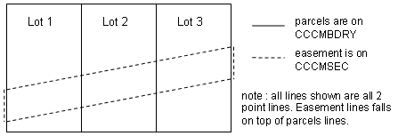
Table 1 Layer Name Description AutoCAD object CCCMBDRY All primary boundaries dealt with by the plan other than natural boundaries. line or arc update dataset CCCMSEC All secondary boundaries dealt with on the plan, other than natural boundaries. (i.e. easement). line or arc update dataset CCCMTIE All tie lines. (see paragraph 20). line update dataset CCCMBDRYNAT All primary natural boundaries dealt with by the plan. polyline update dataset CCCMSECNAT All secondary natural boundaries dealing with easements and rights of ways dealt with by the plan. polyline update dataset CCCMCONDOx All condo units with each floor placed on a different layer. Each floor layer shall be uniquely labelled CCCMCONDOx, where "x" is a unique value for each floor. polyline update dataset - CCCMBDRY contains the primary boundaries dealt with by the plan. (i.e. if the purpose of the plan is to create new parcels, all boundaries except natural boundaries of the new parcels shall be present on this layer. Similarly, if the purpose of the plan is to create an easement only, all boundaries of the easement other than the natural boundaries shall be represented on CCCMBDRY layer.)
- CCCMSEC contains all secondary boundaries dealt with by the plan.
(i.e. if the purpose of the plan is to create parcels as well as
easements, the parcel boundaries shall be represented on CCCMBDRY and
the easement boundaries shall be represented on CCCMSEC in order to
avoid conflicts between the line works.) Information on CCCMSEC layer
should only exist if two or more types of boundaries are dealt with
by the plan. Only non-natural boundaries shall be present on this
layer.
Figure 1
- CCCMBDRYNAT contains all primary natural boundaries dealt with by the plan. (i.e. if the purpose of the plan is to create new parcels, only the natural boundaries of these new parcels shall be represented on the CCCMBDRYNAT layer.) Only primary natural boundaries shall be present on this layer.
- CCCMSECNAT contains all secondary natural boundaries dealt with by the plan such as natural boundaries of an easement. If the easement is bounded by a natural boundary that segment of the easement shall be on the CCCMSECNAT layer. Information on CCCMSECNAT should only exist if two or more types of natural boundaries are dealt with by the plan. Only secondary natural boundaries shall be present on this layer.
- CCCMTIE contains all the other measured boundaries and connections to survey monuments and nearby control survey markers. All tie lines on CCCMTIE shall be shown in full length. (i.e. if a tie is made to a control point 2 kilometres away, the line on CCCMTIE will be completely shown at its true length, but may be shown as broken on the plan.) Other traverse lines shall not be shown on this layer.
- CCCMCONDOx contains the boundaries of all condominium units. Each unit shall form a closed polygon and all unit boundaries shall be an accurate representation of the unit boundaries represented on the plan. Each unit shall be spatially oriented relative to the parent parcel. The parent parcel is to be shown on the CCCMBDRY layer. For multi-floor condominiums, each floor shall be placed on a separate layer in the digital file. Each floor layer shall be uniquely labelled CCCMCONDOx, where "x" is a unique value for each floor (e.g. "0" for basement, "1" for first floor, "2" for second floor , etc.). Common areas are not to be shown in the digital spatial file.
- Line work in details shall not be placed on the CCCMBDRY, CCCMBDRYNAT, CCCMSEC, CCCMSECNAT, CCCMTIE or CCCMCONDOx layers. Line work on these layers shall represent the main body of the plan, even if not visible at plotting scale.
Topology and Structure
- All boundaries and ties must be represented by lines.
- All lines must be topologically correct on the layer itself, but not between layers. (Note: Natural boundary layers such as CCCMBDRYNAT and CCCMSECNAT must be topologically correct with their corresponding CCCMBDRY or CCCMSEC layer.)
- The following rules are to be followed for each layer (unless
indicated otherwise) to ensure properly structured data:
- no duplicate lines within a particular layer;
- no overlapping lines within a particular layer;
- no crossing lines on CCCMBDRY and CCCMBDRYNAT;
- no undershoots and overshoots (see figures 2 and 3);
- at corners or intersections, all lines must converge to the same point. Situation where a small triangle, a small gap or a small line is created must be avoided and corrected (see figures 4, 5 and 6);
- the line types must be one of the following AutoCAD object:
- Straight line are to be of type LINE;
- Curved lines are to be of type ARC; and
- Natural features and condominium units are to be of type POLYLINE.
- each line of the same nature shall be broken at monuments (no gaps), deflections and intersections. Lines shall not be broken at other points such as traverse hubs; and
- the data must be 2-dimensional (i.e., Z value = 0).
 Text
description of Figure 2
Text
description of Figure 2
Figure 2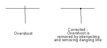 Text
description of Figure 3
Text
description of Figure 3
Figure 3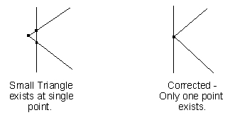 Text
description of Figure 4
Text
description of Figure 4
Figure 4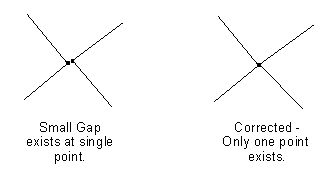 Text
description of Figure 5
Text
description of Figure 5
Figure 5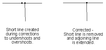 Text
description of Figure 6
Text
description of Figure 6
Figure 6
Main monuments coordinate file
- The coordinates of the main monuments and the control survey markers that appear on the plan to geo-reference the survey shall be provided in a text file along with the reports (see paragraphs 7, 8 and 28 of this chapter). These coordinates must be provided if the survey is geo-referenced (see paragraph 10 of this chapter).
- The format for this text file will be point ID, Northing, Easting,
Orthometric Height (if available) and Scale Factor (if available)
with all text elements separated by a delimiter (Comma "," or pipe
sympol "|") and with each point on a separate line.
Example:
[Point ID] [, or |] [Northing] [, or |] [Easting] [, or |] [Orthometric Height] [, or |] [Scale factor]
200,5183075.467,344077.656,265.54,0.999623
201,5183073.253,344241.115,265.40,
60,5183256.62,344434.93, ,
Note: The comma cannot be used as a delimiter when it is also used as the decimal placemark (International System of Units, French notation).
Report
- If the digital spatial files and the main monuments coordinate
file (if applicable) are submitted by means other than by CLSS
On-Line submission form, the survey report shall include the
following additional information on the spatial file (note: the
On-Line submission form is being developed):
- an outline of what was used to geo-reference the digital spatial file (see paragraphs 9 and 11 of this chapter);
- the combined scale factor(s) (see paragraph 13 of this chapter);
- the bearing correction between the plan and digital spatial file bearings (may be zero) (see paragraph 14 of this chapter); and
- for geo-referenced surveys, the estimated absolute accuracy of the survey at the 95% confidence level (see paragraph 9 of this chapter and the appendix E1-Glossary for definition).